 |
|
 |
|
| Sysmatec |
|
|
|
 |
 |
 |
|
|
Visual interface creation with the software Siam: Application to a fermentor automation.
This page shows the basic principles of the software Siam with an exemple.
|
|
|
|
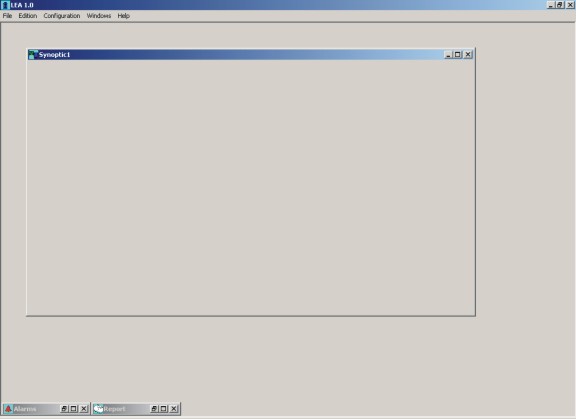
Step 1: open an new window
An empty window appears (figure 1)
|
|
 |
|
|
| Figure 1 A new 'Synoptic' window |
|
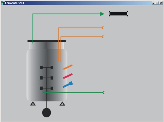
| Step 2: Import an image
It can for exemple show the installation to automate (figure 2).
|
|
 |
|
|
| Figure 2 A 'Synoptic' window with a bitmap image |
|
| Step 3: Add visual components to the window
These visual components are selected in an object toolbox (figure 3).
|
|
 |
|
|
| Figure 3 The visual object toolbox |
|
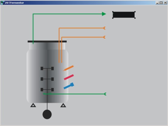
| The component is first selected in the toolbox and appears in the window on the place where the user clicks (figure 4). This object can be moved or deleted as long the configuration mode is activ. |
|
 |
|
|
| Figure 4 Add a visual component to a window |
|
| Step 4: link a channel to this component
To link a channel (actual value, setpoint, etc...) from a device (like a balance, an A/D converted, etc...) to a visual component, the user cliks on the component with the left mouse button. A popup menu appears (figure 5).
|
|
 |
|
|
| Figure 5 Menu popup permettant le choix du canal à visualiser |
|
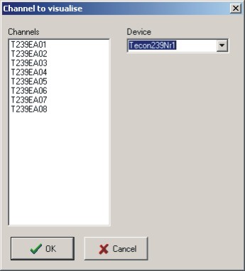
| By clicking on Channel choice, a new window appears. The user can select the channel he wants to link with the component (figure 6). |
|
 |
|
|
| Figure 6 List of channels wich can be linked to the component |
|
| Step 5: Configuration of the linked channel
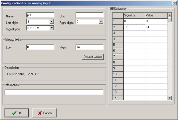
The linked channel has a default configuration. To check it and to modify it, the user has again to click on the component with the left mouse button. By clicking on Channel configuration in the popup menu, a new window (figure 7) appears. The user can for exemple modify the channel name and calibrate the channel.
|
|
 |
|
|
|
| Figure 7 Dialog for the configuration of an analog input (here for exemple the Tecon 239 interface box) |
|
| Step 6 and following: repeat the same operation for every component to display (step 3 to 5)
The device (here the Tecon 239 interface box) can then be connected and the communication can be started.
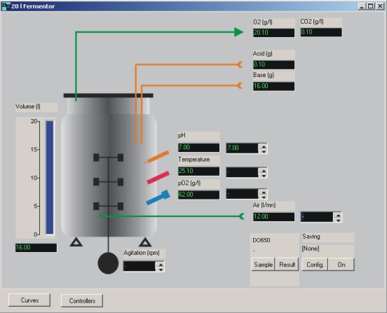
An exemple is presented below (Figure 8). It is also very easy to create windows with curves.
|
|
 |
|
|
| Figure 8 An exemple: fermentor automation |
|
| These configuration can be modified or completed later. The software offer here a high degree of flexibility, for exemle to add new devices like balances, new probes, etc... |
|
| Contact |
|
Top
|
|
Sysmatec
Oberdorfstrasse 51
CH 3930 Eyholz
tel + 41 27 946 80 18
fax + 41 27 946 86 42
info@sysmatec.ch |
|
|
|
|
|
|
|
|
|
|
|
|
|
|
|
|
|


